

Technicians dispatched for “encoder fault” or “unexplained mis-leveling” sometimes replace the feedback device twice — while the root cause is mechanical slip at the traction sheave. A widely cited Elevator World field analysis (John W. Koshak, 2021) documented how steel particles under the sheave correlated with rope tension differences far outside code limits, long before the sheave required replacement.
This article provides a comprehensive examination of the relationship between suspension rope tension, traction sheave condition, and drive feedback accuracy — connecting mechanical maintenance to electronic diagnostics in a way that high-frequency troubleshooting searches often miss.
1. Suspension Rope Systems in Traction Elevators
1.1 How Ropes Transfer Power
Traction elevators use steel wire ropes or belts to suspend the car and counterweight from a traction sheave driven by an electric motor. The fundamental principle is friction: the ropes grip the grooved surface of the traction sheave, and as the sheave rotates, the ropes move, raising or lowering the car. The counterweight, typically equal to the car weight plus 40–50% of rated capacity, balances the system and minimizes the motor torque required for operation.
A typical geared traction machine uses 4–6 suspension ropes in a set. Each rope must carry an approximately equal share of the total load. When one rope carries significantly more than its share, the sheave groove experiences uneven wear, microscopic slip occurs, and position feedback diverges from actual car position.
1.2 Rope Construction and Wear Mechanisms
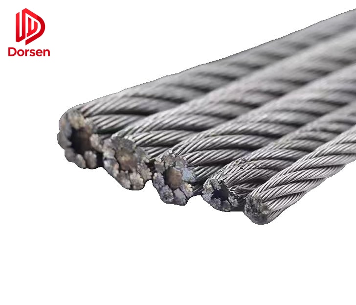
Modern elevator ropes use multiple strands of high-carbon steel wire with a fiber or steel core. Key wear indicators include:
| Parameter | Measurement method | Discard criterion (typical) |
|---|---|---|
| Rope diameter | Caliper at multiple points | > 10% reduction from nominal |
| Broken wires | Visual count per lay length | Per manufacturer and code limits |
| Core condition | Probe or bend test | Core collapse or corrosion |
| Lay pattern distortion | Visual comparison | Birdcaging, kinking, or flattening |
| Lubrication state | Visual and touch | Dry, cracked, or contaminated |
Rope diameter reduction increases unit pressure in the sheave groove, accelerating groove wear and creating a feedback loop: worn groove → more slip → more wear → more slip.
2. Equal Tension Requirements
2.1 Code Definition
ASME A17.1 / CSA B44 defines equal suspension member tension as:
The lowest measured tension is within 10% of the highest measured tension in the set.
EN 81-20 carries equivalent requirements for European installations. This is not a suggestion — it is a maintenance requirement enforced during periodic inspections.
Yet field telemetry cases have recorded dynamic tension spreads of 500 lb (227 kg) or more between ropes in the same set during normal travel, while visible metal dust already accumulated under the machine. Such imbalances violate code by a factor of five or more.
2.2 Static vs. Dynamic Tension Measurement
| Method | When measured | What it reveals |
|---|---|---|
| Static tension | Car at rest at a landing | Resting load distribution |
| Dynamic tension | During a full run cycle | Load shifts during acceleration and deceleration |
| Telemetry logging | Continuous during operation | Time-series tension per rope — reveals transient imbalances |
Static measurement alone can miss dynamic imbalances that only appear during acceleration. Telemetry systems that log per-rope tension during a full run reveal problems invisible at rest — and are increasingly used on high-cycle commercial installations.
2.3 Tools for Tension Verification
- Mechanical rope gauges — spring-loaded devices that measure deflection under known force; field accuracy commonly cited around ±2.5%
- Electronic tension meters — load cell based; higher accuracy (±1%) but require calibration
- Telemetry systems — permanent installation with per-rope sensors; provide continuous monitoring and alert thresholds
- Straightedge and feeler gauges — for sheave groove depth measurement after tension correction fails
3. How Unequal Tension Creates “Encoder-Like” Faults
3.1 The Slip Mechanism
When one rope carries significantly more load than others during travel:
- The sheave groove experiences uneven wear on the overloaded rope path
- Ropes slip microscopically relative to the sheave — invisible to visual inspection
- Position feedback (encoder or tape) counts pulses based on sheave rotation, not car position
- The controller logs speed or position faults as cumulative error grows
The encoder is functioning correctly — it accurately reports sheave rotation. But sheave rotation no longer equals car travel because of rope slip. This is why replacing the encoder does not fix the problem.
3.2 Symptom Overlap with True Encoder Failure
| Symptom | Rope slip indicator | True encoder failure indicator |
|---|---|---|
| Mis-leveling worsening over weeks | Yes — slip accumulates gradually | Possible but usually sudden |
| Intermittent position drift on long runs | Yes — slip increases with distance | Possible — signal noise |
| Return-to-terminal after cumulative error | Yes — controller corrects large drift | Yes — lost pulses |
| Metal particles near sheave | Strong indicator of slip | Not associated |
| Two shaft-learn runs differ > 3 mm | Yes | Yes — investigate both causes |
| Sin/Cos voltage imbalance | No — mechanical issue | Yes — electrical issue |
Diagnostic implication: If two shaft-learn runs differ by more than 3 mm per floor, investigate both encoder signal integrity and rope slip before ordering replacement parts.
3.3 The Chalk Mark Test
A simple field test for traction slip:
- Mark the rope against the sheave at one floor landing
- Run the car one full floor up and return to the starting floor
- Measure mark drift on the sheave relative to the rope
Field acceptance used by many crews: single-floor slip under 5 mm on both empty and loaded runs. Greater drift confirms slip and should trigger rope tension measurement before any electronic component replacement.
4. Field Evidence: Particles Mean Action Now
4.1 Case Study Summary
Koshak’s documented case involved a seven-year-old geared traction unit running roughly 1,700 trips per day in a commercial building. Key findings:
- Metal dust under the counterweight-side pinch point appeared while rope tension telemetry showed daily alerts
- Dynamic tension spread exceeded 500 lb (227 kg) between ropes in the same set
- The sheave showed uneven groove wear on the overloaded rope path
- Waiting until the sheave was visibly damaged turned a tensioning task into a sheave and rope replacement debate between owner and contractor
4.2 Maintenance Rule
Any visible grinding debris near the driving sheave triggers immediate rope tension measurement and equalization — before ordering electronic parts.
This rule is adopted by informed maintenance crews worldwide. Metal particles are not cosmetic — they are evidence of steel-on-steel grinding at the traction interface, and the grinding accelerates with every trip until corrective action is taken.
5. Rope Tension Verification Workflow
5.1 Step-by-Step Procedure
Step 1: Visual check for metal particles at sheave pinch points
Step 2: Measure dynamic or static rope tensions on all ropes in the set
Step 3: Calculate spread — highest vs. lowest tension
Step 4: Equalize to within 10% if spread exceeds code limit
Step 5: Confirm anti-rotation devices present and functional
Step 6: Re-test ride and shaft-learn data (two-run comparison)
Step 7: Inspect groove depth and rope diameter if 10% cannot be achieved
Step 8: Plan sheave regrooving or rope replacement if wear exceeds limits
5.2 If 10% Cannot Be Achieved
When equalization to within 10% is not possible after adjustment:
- Measure rope diameter against discard criteria at multiple points along each rope
- Measure sheave groove profile and depth with groove gauge
- Evaluate regrooving if permitted by manufacturer data and remaining groove depth
- Plan sheave and/or rope replacement if wear is beyond limits
- Document findings for owner communication — deferred action increases cost
Steel wire rope material has not fundamentally changed in decades. Neglected tension maintenance remains the dominant preventable factor in premature sheave damage across all traction machine brands.
6. Anti-Rotation Devices
6.1 Purpose and Code Requirements
Anti-rotation hardware prevents rope twist and uneven loading at shackles. When ropes rotate along their axis, individual strands bear unequal load, accelerating wear and contributing to tension drift over time.
Code commentary under ASME A17.1 and EN 81-20 notes that anti-rotation devices must conform to current requirements. When ropes are retensioned or replaced:
- Verify anti-rotation devices are present on every rope in the set
- Inspect for damage, deformation, or missing components
- Replace devices that no longer prevent rotation under load
- Confirm device type matches current code edition (requirements have tightened over decades)
Missing or damaged anti-rotation devices are a frequently overlooked contributor to tension drift that reappears weeks after equalization.
7. Sheave Groove Maintenance
7.1 Groove Wear Measurement
| Measurement | Tool | Accept/Reject |
|---|---|---|
| Groove depth | Groove gauge or radius template | Compare to manufacturer minimum |
| Groove profile | Contour gauge | U-shaped profile must be maintained |
| Surface hardness | Not field-measurable | Replace if visual scoring is deep |
| Rope seat contact | Visual — rope should contact groove bottom | Gap indicates worn groove |
Worn grooves reduce friction coefficient, increasing slip tendency regardless of rope tension. A sheave with worn grooves cannot maintain traction even with perfectly equalized ropes.
7.2 Regrooving vs. Replacement
| Factor | Regrooving | Replacement |
|---|---|---|
| Remaining groove depth | Must exceed minimum after regroove | N/A — new sheave |
| Sheave material hardness | Must be sufficient for re-machining | New hardened surface |
| Cost | Lower — machining only | Higher — new component + installation |
| Downtime | Hours | Half day or more |
| Rope compatibility | May require new ropes to match profile | New ropes recommended |
8. Annual Maintenance Program Integration
Integrate these tasks into MCP (Maintenance Control Program) documentation:
| Task | Minimum frequency | Notes |
|---|---|---|
| Rope tension check and adjustment | Annual (more often on high-cycle units) | Use calibrated gauge |
| Rope diameter measurement | Annual | At 3+ points per rope |
| Sheave groove measurement | Annual | Compare to manufacturer limits |
| Anti-rotation device inspection | At every rope service | Replace if damaged |
| Encoder shaft coupling inspection | At every drive-related callback | Check for slip independent of rope |
| Metal particle visual check | Every machine room visit | Immediate action if found |
Treating rope and feedback as one integrated system — not separate subsystems — reduces repeat callbacks and unnecessary parts expenditure.
9. Procurement Angle for Parts Suppliers
When customers request encoders for repeated position faults, ask these diagnostic questions before processing the order:
| Question | If “no” — recommend first |
|---|---|
| Has rope tension been verified within 10%? | Tension measurement and equalization |
| Was metal dust present in the machine room? | Sheave and groove inspection |
| Do two shaft-learn runs differ by more than 3 mm? | Investigate both slip and encoder |
| Has the chalk mark slip test been performed? | Simple slip test before part order |
| When were ropes last replaced or equalized? | Maintenance history review |
A correctly supplied encoder cannot compensate for ongoing traction slip. Supplying parts without diagnostic context creates repeat orders, warranty claims, and customer dissatisfaction.
10. Related Components and System Thinking
| Component | Relationship to rope tension |
|---|---|
| Traction sheave | Direct wear partner — groove condition affects slip |
| Encoder / feedback device | Reports sheave rotation, not car position — slip creates false errors |
| Rope equalizing hardware | Maintains tension balance — inspect at every service |
| Compensation chain / hitch | Affects load distribution — check for wear and equal length |
| Governor rope | Separate system but same tension principles apply |
DORSEN provides OEM-compatible encoders, traction sheaves, wire ropes, and tension measurement equipment for maintenance contractors worldwide. Diagnose the mechanical foundation first — then match the part with confidence.